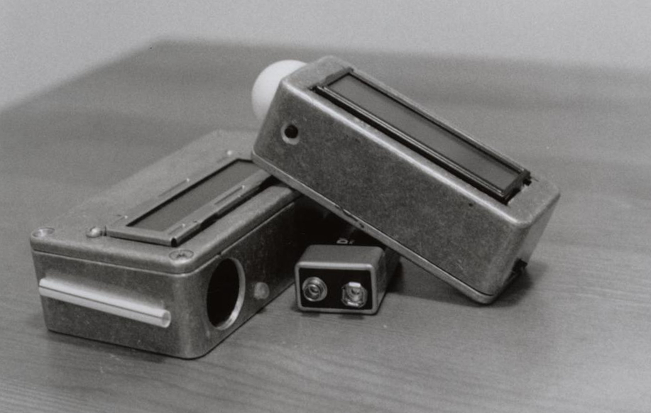
Homemade digital spot meter, left, and incident meter, right.

Homemade digital spot meter, left, and incident meter, right.
As I purchased and made more and more meterless cameras, I found myself needing a light meter, in particular a "spot meter", which is capable of reading the brightness of a small portion of a given scene while ignoring the rest. Spot meters are somewhat pricy at several hundred dollars. Since I only rarely needed one, I could never seem to justify spending several months of film and paper on one (at this season of my life, I mentally weigh purchases by considering how much sensitized material I could otherwise buy. Units used for this purpose in the past include cases of paintballs, packages of raman noodles, record albums, ammunition, and motorcycle parts).
I decided I should like to build a full-functioning spot meter on a budget of $20 or less. The first step was designing the optics. I still have never owned or used a commercial spot meter, but the only scheme I could come up with to measure a small spot of a scene was to use an image-forming lens and put a small sensor at the focal point or on the "film plane" so that only a small part of the scene was intercepted by the sensor. I wanted a "spot size" of 5 degrees or less, and knowing the focal length of lens that would fit in my enclosure, I could thus estimate how big my sensor needed to be--only a few mm^2.
Immediately I considered a silicon photodiode, but balked at implementing it in an actual light meter. A photographic exposure meter needs to be able to read 16 stops or more of light, which is factor of over 65,000 in intensity. Photodiodes have both a dark current and a saturation current, and I didn't want to fool with any amplification circuitry to match my Atmel microcontroller's ADC. I ended up using a the TSL230R light-to-frequency chip. For $6, this IC provides a pulse train that can be digitally read by a microcontroller. It uses a photodiode array to drive an onboard oscillator and frequency-divider. The output oscillates at a frequency that is proportional to the light intensity falling on the photodiodes. There are 3 decades of sensitivity adjustment and 3 decades of onboard frequency division, so nearly any intensity level can be handled. The only worry was spectral response and low-end sensitivity. Since I needed to be able to take a measurement fairly instantly, I needed the chip to oscillate at at least 100Hz even at the lowest interesting light level. I determined that if the chip oscillated too slowly, I could gain the sensitivity back by using a shorter lens and settling for a wider "spot size" to intercept more light. Infrared sensitivity can be compensated for with a common IR highpass filter from any digital camera sensor. So all I had to do was place the sensor at the focal plane of a lens and I would have a spot meter. The rest was just details.

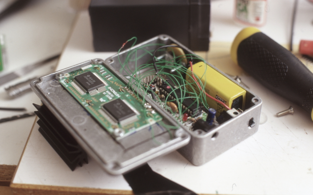
I used a single element, coated lens and splurged on a nice aluminum case. I used a Boarduino clone from AVRThing.com. This is an Arduino-compatible board that is much smaller than the original Arduino board. Even smaller Arduino compatible boards are available now. A 9v battery just barely fits in the case. With miscellaneous components, I was slightly overbudget, but I figured if it didn't work I could use the parts for other things. A lot of cost could be cut by using a simpler microcontroller, but the Arduino platform is what I am familiar with from my other electronics projects, and I already had LCD code.
The toughest part for me was writing the microcontroller code which is currently at about 700 lines; writing the program such that the various functions would all operate reliably and sensibly was a hefty challenge for my crude programming skills. I needed to read the chip frequency, transparently auto-scale the chip sensitivity, interpret the chip data, and display the results in an interactive and user-friendly way on the LCD. The light-to-frequency chip is connected to an interrupt pin on the microcontroller, incrementing a variable at every pulse. The main program loop constantly calculates the chip frequency and stores it in memory every 10ms. If it detects that the chip is operating at too high or too low of a frequency, it will call a function that changes the sensitivity of the chip to keep the chip oscillating in an ideal frequency range of 100Hz to 50kHz. When the trigger button is pressed, the chip frequency is run through a series of conversions to correct it for the current sensitivity settings. It is then converted to photographic Exposure Value with a calibration function which I charted by metering a gray card with my Nikon F801. Depending on the current readout mode and film speed, appropriate exposure setting recommendations are calculated and displayed on the LCD.
There are three modes--Aperture Priority, Shutter Priority, and EV_(100). After a reading is taken, the user can flip through various aperture and/or shutter speed options and the meter will auto-update the exposure recommendations without having to re-shoot the scene. Switching modes is done by holding down the trigger while booting the meter. Then input routines run that allow you to set EV, Shutter Priority, or Aperture priority, and film speed if applicable, with a few trigger clicks. However, when you turn the meter off, the latest settings are saved in the microcontroller's EEPROM, so that whenever you turn the meter back on, it retains the mode, input settings, and film speed last used.
Overall the meter works very well. It is a bit bulky and doesn't last terribly long on a battery (about 12 hours). It works very well for metering stage performers or landscape elements however. I added functionality to the program so that the device can also be used as a transmission densitometer, enlarging meter, and as an incident meter, making it truly a flexible and useful device.

After I added the incident-reading mode to the original meter, I found myself using the "spot meter" as an incident meter 90% of the time. I also found that I left it at home a lot because of its bulk. Since an incident meter would be much simpler to make and I already had the code written, I made a sister meter that operates in incident mode only. The second meter is much smaller, much lighter, and is very handy. It is barely bigger than a box of 120 film, and lasts practically forever on a battery since it uses a 1000mAh cell phone battery and a 5v boost IC. The spot meter uses a 160mAh 9v battery behind a power-wasting LM7805 linear voltage regulator. Despite its relative simplicity, it's the incident meter that I consider the greater accomplishment. Although the spot meter is more versatile, I rarely use its enlarging meter or densitometer functions. The new incident meter does only one thing, but it does it well enough and with such user-friendliness that I find myself using it much more. I have learned to avoid featuritis for my projects and make things that do one thing well.